

Inroduction and intended use
hank you for choosing EasyLap timing system.
With the EasyLap system you have purchased a Professional time and round measurement system for the RC car Racing. This allows you an accurate timekeeping for RC car different scale for training purposes of for holding a race. The permissible voltage and polarity of the individual components must be observed! Operation under adverse ambient conditions is not allowed, these include:
-High humidity
-Wet conditions
-Dust or combustible gases, vapors, solvents or benzene
-High temperature (> approx.+40℃)
-Heavy vibrations
Any other use of this product apart from the description above is not permitted and can not only damage the product, but can also lead to short circuits, fire, electrical shock and personal harm. Hence, the product must not be changed or converted!
Important safety advices
-Before you start using, please make sure that you have read this manual! Keep this instruction manual in a safe place for later reference. EasyLap is not liable for any warrantee claims or damages that occur from a nonobservance of this manual.
-Electronic devices and accessories are not suitable for children under 14 years! They are not toys and children should be carefully advised.
-The components should be regularly checked for damages, especially damages on the mains cable. In case of a damage, the product must not be used until it is repaired by a qualified person.(See our contact details at the end of this manual for further advice).The housing must not be opened! When opening the case, any claim under warranty or guarantee expires.
-Protect form dust, moisture, direct sunlight, heat and rain. This can lead to malfunctions and damage the electronics.
-Keep it away from transmitters (cell phones, remote controls, WiFi router etc...) as their EMF can interfere the electronics.
-Disconnect the interface it is not used.
-If you may assume, that the unit cannot be used safely any more, you must immediately stop using it and secure it against unintended operation. Such an assumption may be if the unit:
-is apparently damaged.
-shows malfunctions
-is stored in an adverse environment for prolonged periods of time.
Installation
Basic function:
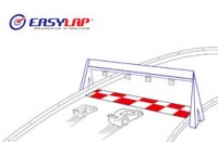
The EasyLap timing system operates with the transmission of infrared light, like a ordinary remote control of TV or VCD. This means the transponder sends the information signal via infrared light to the bridge receivers. This signal is processed by the interface and then delivered to the PC software. So it is absolutely necessary for the transponder to have a clear line of sight with the bridge receiver. To ensure this, place the transponder just below the window of the body. The receiver modules can be placed one a bridge above the track. So it is possible to drive with as much cars as you like at the same time.
Bridge receiver modules:
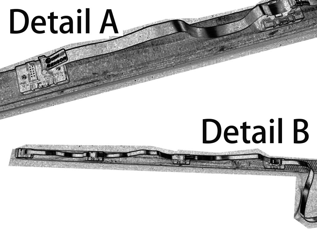
In the EasyLap timing system kit there are 4 receiver modules included. But how much modules you need depends on your track width and the height of your bridge. Following values for the beginner are recommended:
Height of the bridge:50-100cm
Distance between the receiver modules: about 30cm
For example if you have a track width of 150cm and you place the receiver modules with a distance of 30cm from each other on the bridge, you need 4 receiver modules.
Basically the higher the bridge, the larger the reception range of the receiver module and the less modules are needed. But the height of the bridge should also not be too high because the signal strength decreases with the height.
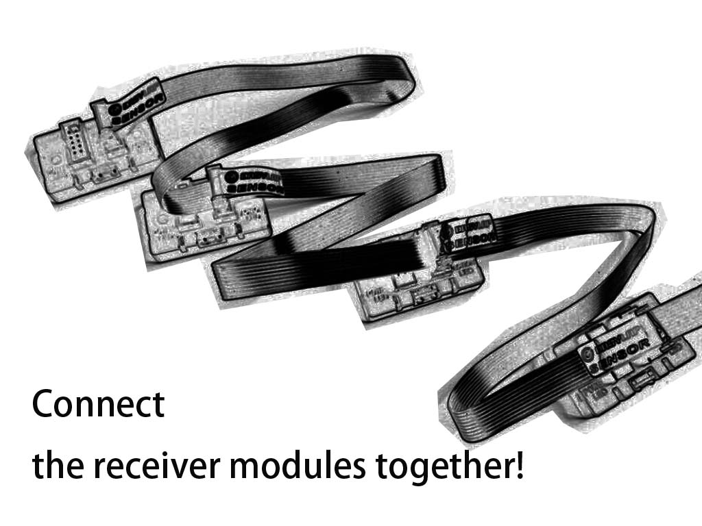
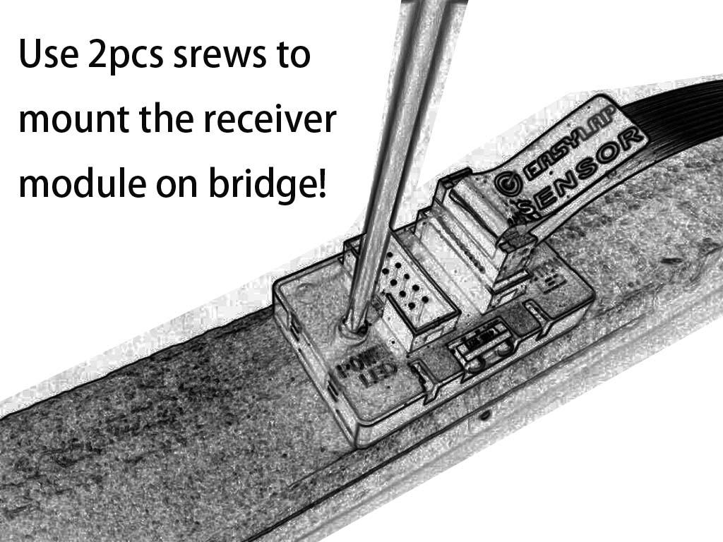
If you have mounted the receiver modules on the bridge you have to connect them together with the delivered flat cable. This flat cable has 5 connectors. 4 connectors to the receiver modules and 1 connector to the interface. If your track need to add receiver module as you want.
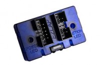
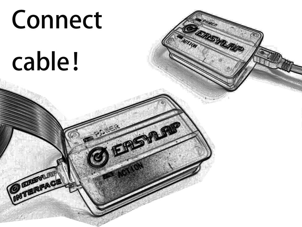
Interface:
If the bridge (not included) is ready, you can connect the interface with the flat cable to the receiver modules. To avoid interferences the distance between the interface and the bridge should be as short as possible.
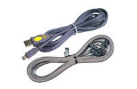
On the interface you find a Mini-USB connector for the communication with the PC.
When connected, the red Power-LED should light up. At initial installation, this process can take a few seconds, the driver is installed automatically. When putting on also the blue Action-LED should flash briefly.
Transponder:
When you mount the transponder inside your model you have to search for a position where the transponder has direct visibility with the bridge. Otherwise the infrared signal is not delivered to the receiver modules. The transponder can be connected directly to the radio receiver in the model. If you use a receiver pack (for example in 1/10 RC nitro cars)you should only use 4-5 cell receiver packs.
First operation
If the system is ready, you can install the Zround software on your PC. The setup files of Zround program can be download this link below.
https://www.zround.com/index.php/download-mananger/
Adjust Lap counter setting:
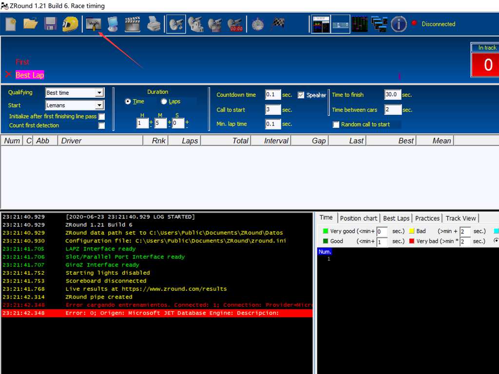
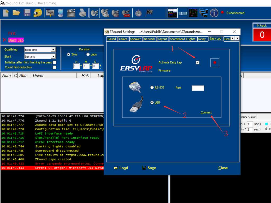
Now you should adjust the right Lap counter model. This configure page you can choose when clicked “Options”button on the top menu. Lap counter model you have to choose EasyLap.
You now have to choose USB option and let Active Easylap option checked. Once these settings are done click on the connect button. You should now see Easylap comport opened.
For more information about the operation of Zround Software, click the link below for more help!
Technical Data
Interface:
Input Voltage: USB Current consumption: ca. 50mA Dimensions: ca. 60 x 50 x 22 mm Weight: ca. 33g
Transponder:
Input Voltage: 4 – 5 cells NiMH (4 – 6 V) Current consumption: ca. 11mA bei 6V Dimensions: ca. 17 x 13 x 7 mm (w/o cable) Weight: ca. 3g (incl. cable)
Warranty
With the purchase of this product you purchased at the same time a one year warranty from date of purchase. The guarantee applies only to the already existing material defects on the purchase of the product and / or functional defects.
Excluded from the guarantee are:
• Damage caused by incorrect use
• Damage caused by neglect of duty of care
• Damage caused by improper handling and maintenance errors
• Liquid damage
For warranty claims, please contact your local dealer. Should it be necessary to send the product, you must enclose a copy of the invoice and a repair order. You can download it at www.myezlap.com. With direct sending to the service department must be consulted beforehand (held by e-mail). The postage costs borne by the consignor. Paid packages are not accepted. Every sent in warranty case is first examined on admissibility by our service department. For rejected warranty claims a control and processing fee will be charged before we return the product. Repairs not covered under warranty must be paid before the start of the repair.
Products shall be subject to any changes without additional notices;
Welcome to visit http://www.myezlap.com for further products' details..
Note:Bridge is not included in this set!